
Cruise Report: R/V Surf Surveyor Cruise S1-00-CL, Mapping the Bathymetry of Crater Lake, Oregon, 2000
The Kongsberg Simrad EM1002 High-Resolution Multibeam Mapping System
There are several different brands of high-resolution multibeam mapping systems that are appropriate for shallow-water surveys. After a review of the currently available systems, we chose to use for this cruise the Kongsberg Simrad EM1002 system because; (1) it is the latest generation of high-resolution multibeams with a frequency appropriate for the known depths of Crater Lake, (2) it is based on the highly successful EM1000 system, (3) it has the ability to map large areas at high speed without compromising data quality and, most importantly, (4) it has the ability to simultaneously produce high5 resolution, calibrated backscatter imagery. We used an EM1002 system owned and operated by C&C Technologies, Inc. (Lafayette, LA) installed aboard the 26-ft Surf Surveyor (Fig. 5) for the Crater Lake survey.
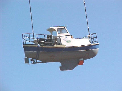 |
| Figure 5. RV Surf Surveyor. |
An overview of high-resolution multibeam mapping systems can be found in Hughes-Clarke et al. (1996). The Simrad EM1002 system operates at frequencies of 98 kHz (inner ±50° swath centered at nadir) and 93 kHz (the outer ±20°) from a semi-circular transducer (Fig. 6) mounted on the forward edge of the keel. The system was designed to operate in several modes through a range of depths from 5 to approximately 800-m. The shallow (ultrawide) mode, used to maximum depths of about 200 m, forms 111 receive beams with a spacing of 2° distributed across track and 2° wide along track. The beam geometry can generate up to a 150° swath that can cover as much as 7.4 times the water depth. The wide mode is used for depths between 150 and 400 m, and the deep mode is used for depths of greater than 400 m. There are options within each mode for beam distribution (equiangular or equidistant) and pulse lengths (0.2, 0.7, and 2 ms). The specific options used for the Crater Lake survey are discussed in the data processing section below.
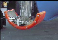 |
| Figure 6. Simrad EM1002 transducer. |
Most conventional vertical-incidence echo sounders determine the time of arrival of the returned pulse (and thus the depth) by detecting the position of the sharp leading edge of the returned echo, a technique called amplitude detection. In multibeam sonars, where the angle of incidence increases for each consecutive receive beam to either side of the vertical, a returned echo loses its sharp leading edge and the accurate depth determination becomes inaccurate. To address this problem, the EM1002 multibeam system uses an interferometric principle in which each beam is split, through electronic beamforming, into “half beams” and their phase difference is calculated to provide a measure of the angle of arrival of the echo. The point at which the phase is zero (i.e., where the wavefront of the returned echo is normal to the center of the receive beam) is determined for each beam and provides an accurate measure of the range to the lake floor. Both amplitude and phase detection are recorded for each beam and then the system software picks the “best” detection method for each beam, based on a number of quality–control measurements, and uses this method to calculate depth.
The EM1002 also provides quantitative seafloor-backscatter data that can be displayed in a sidescan-sonar-like image (see Maps section below). The backscatter images can be used to gain insight into the spatial distribution of seafloor properties. A time series of echo amplitudes from each beam is recorded at 0.2- to 2.0-ms sampling rate, depending on the water depth. The echo amplitudes are sampled at a much faster rate than the beam spacing and can be processed from beam-to-beam to produce a backscatter image with the theoretical resolution of the sampling interval (15 cm at 0.2 ms). The amplitude information can be placed in its geometrically correct position relative to the across-track profile because the angular direction of each range sample is known. The EM1002 software corrects the amplitude time series for gain changes, propagation losses, predicted beam patterns and for the insonified area (with the simplifying assumptions of a flat seafloor and Lambertian scattering). Subsequent processing (see Processing section below) uses real seafloor slopes and applies empirically derived beam-pattern corrections to produce a quantitative estimate of seafloor backscatter across the swath.
***previous*** — ***next***