
Cruise Report: R/V Surf Surveyor Cruise S1-00-CL, Mapping the Bathymetry of Crater Lake, Oregon, 2000
The Maps
The overview maps of backscatter and shaded relief that accompany this report were generated from larger-scale subarea maps (Fig. 11). The 2-m-resolution subarea maps were combined to produce the series of overview maps of the entire area (Figs.12 and 13). The detailed subarea maps are 463 m by 675 m in size and were produced at 1 m/pixel, the maximum resolution as determined by water depths and beam angle. Contour maps represent the more traditional method of displaying bathymetry. The contours were derived from the gridded elevations. The resultant contours were smoothed with a 3-point running average for the overview maps. Even at the original contour grid, more than 90% of the data had to be discarded so as to only show some chosen contour interval. A much better representation of bathymetry, using 100% of the data is a shaded-relief map. A shaded- relief map (Fig. 12) is a pseudo-sun-illumination
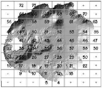 |
| Figure 11. Subarea maps and their area numbers. The resolution of each subarea map is a 2 m/pixel. |
of a topographic surface using the Lambertian scattering law (equation 1), where SI is the pseudo-sun intensity, K is a constant that allows for even background, and ? is the angle between the pseudo sun and the bathymetric surface.
SI = K * cos? (Eq. 1)
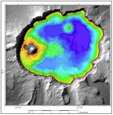 |
| Figure 12. Colored shaded-relief bathymetry (2-m resolution) of Crater Lake. Reddish orange is shallowest, dark blue is deepest. Gray is land (10-m USGS DEM). |
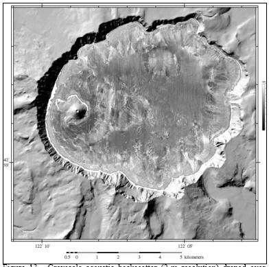 |
| Figure 13. Grayscale acoustic backscatter (2-m resolution) draped over bathymetry of Crater Lake. Lighter tones are higher backscatter. Gray is land (10-m USGS DEM). |
The backscatter map (Fig. 13) is a representation of the amount of acoustic energy, at ~95 kHz, that is scattered back to the receiver from the lake floor. The Kongsberg Simrad EM1002 system has been calibrated at the factory and all gains, power levels, etc. that are applied during signal generation and detection are recorded for each beam and are used to adjust the amplitude value prior to recording. Consequently, the backscatter was calibrated to an absolute reflectance of the lakebed. However, the amount of energy, measured in decibels (dB), is some complex function of constructional and destructional interference caused by the interaction of an acoustic wave with a volume of sediment or, in the case of hard rock, the rock material. The backscatter from sediment is volume reverberation to at least 5 cm caused by lake bed and subsurface interface roughness above the Rayleigh criteria (a function of acoustic wave length; Urick, 1983), the composition of the sediment, and its bulk properties (water content, bulk density, etc.). Although, it is not yet possible to determine a unique geological facies from the backscatter value, reasonable predictions can be made from the backscatter based on the known local geology.
It can not be stressed too strongly that one of the great advantages of this survey is that every sounding of the bathymetry is accurately georeferenced and coregistered with the backscatter. Consequently, each pixel on the map has a latitude, longitude, depth, and backscatter value assigned to it.
***previous*** — ***next***